What’s the principle of OTDR? When the optical fiber propagates, the optical pulse propagated in the optical fiber emits Rayleigh scattering due to the defects of the optical fiber itself and the non-uniformity of the doping components. A portion of the light is scattered back in the opposite direction of the pulse and thus is called Rayleigh backscattering. Backscattered light provides details of the decay associated with a length which is obtained through time.
The distance can be calculated from the time it takes to launch and backward the signal and the speed of light in a glass substance.
This formula can explain how OTDR measures distance:
d=(c×t)/2(IOR)
PS: ① c: the velocity of light in a vacuum; t: The total time between the signal is transmitted and received.
② Because light travels slower in glass than it does in a vacuum, in order to accurately measure distance, the fibers being tested must indicate the refractive index (IOR), which is indicated by the optical fiber manufacturer.
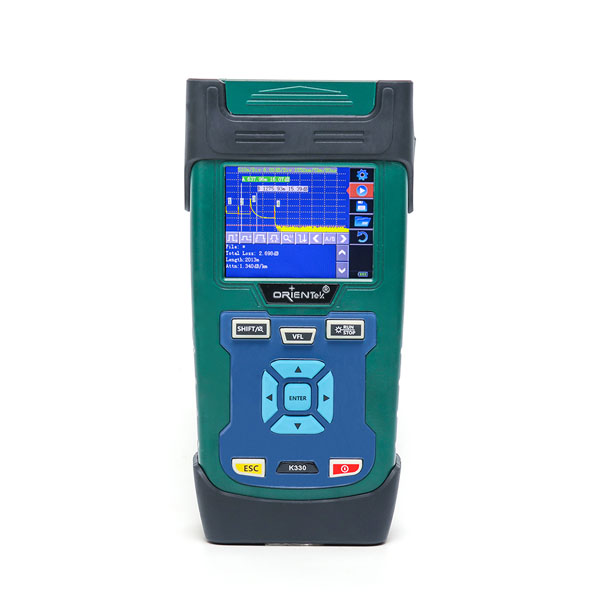
ORIENTEK high precision OTDR K330 is a 1310nm&1550nm wavelength OTDR, 3.5in GUI interface; 1.6m dead zone; 10m ATT dead zone; 130km measure range; 15 hours of standby;10km VFL; up to 32dB dynamic range; over ten thousand storage capacity and so on.
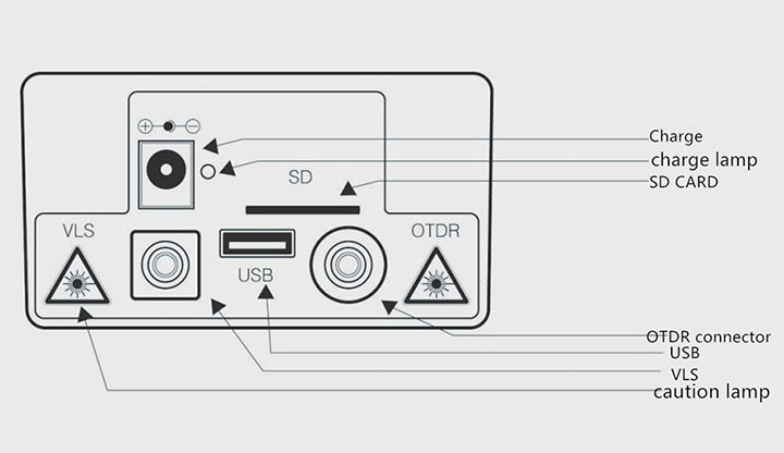
OTDR port
Data port:
USB: it can connect with the PC and import the data to the trace manager software;
SD: insert the SD card
OTDR/VLS: OTDR and VLS optical connector, use FC/UPC connector (optional SC/ST)
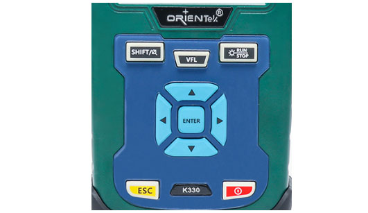
K330 function key
[ENTER]
● Under the main interface, realize the icon function; Pressing this key in the menu action indicates that the current action is in effect;
● When used in combination with the [Shift/∅] combined key, the AB benchmark can be switched
[↑] [↓]
The main function is:
● Move menu bar up and down during menu operation;
● Select the icon to operate on;
● Adjust parameters when setting parameters;
● When used in conjunction with the [Shift/∅] key, contrast display trace lines can be vertically enlarged and shrunk
[←] [→]
The main function:
● Select the parameter you want to modify when setting parameters or performing menu operations;
● The ruler moves left or right during trace operation;
● Help turn the page;
● When used in conjunction with the [Shift/∅] key, contrast display trace lines can be breadthwise enlarged and shrunk.
[ESC]
The main function:
● Cancel current operation;
● Exit parameter setting;
● Convert the contents of the information window;
● Use this in conjunction with the [SHIFT /∅] key to the next event point
[SHIFT/∅]
This key can be used in combination with other keys to achieving composite functions
[ ⦿ ]
Power key
[RUN/STOP]
In the main interface, press the key to start the measurement process; During the test, press this key to stop the test;
[VFL]
Press [VFL] key 2s, VLS connector transmit red light; click [VFL] key, VLS transmit pulse red light; click [VFL] key, stop.
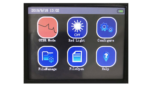
OTDR home page
OTDR home page displays 6 function modules: OTDR Mode, VFL, Configure, FileManage, FileOpen, Help.
Test wavelength selection
OTDR mainly serves optical fiber communication, so the test wavelength should be selected first before optical fiber testing, and 1550nm should be selected as far as possible for single-mode optical fiber. Why? The reason is that the wavelength of 1550nm is more sensitive to the bending loss of optical fiber than that of 1310nm. Whether it is the construction of optical fiber line or the maintenance of optical fiber line, the wavelength of 1550nm is usually selected when testing the whole fiber back-scattering signal curve of a certain optical fiber transmission link by OTDR.
OTDR optic fiber test
OTDR sends a pulse of light into the fiber under test, and immediately begins receiving the returned optical signal and begins calculating the amount of light in the fiber
The "event" distance, the further away the event is, the longer it takes for the reflection to return to the OTDR. The distance can be calculated based on the time it took to receive the event. By examining the curve of the reflected signal, optical transmission characteristics such as optical fiber, a connector can be determined.
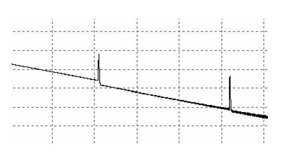
The event points shown on the screen are the abnormal points in the optical fiber that cause the curve to deviate from the straight line, and the events can be divided into reflection events and non-reflection events.
When some light pulse energy is reflected (for example on the connector), the reflection event occurs, and the reflection event generates a spike in the curve, as shown in the figure below.
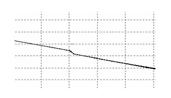
The non-reflective event causes some loss in the whole transmission link of the optical fiber, but the non-reflective event occurs in the part where the light is not reflected
A drop in light power is generated on the curve, as shown in the figure below.