Operation steps of Optical Fiber Welding Machine
Operating tools: fibre Optic Heat shrink Tube, skin Clippers, Fiber Cutter, Dust Free Paper, Alcohol
Open welding machine:(In order to get good welding quality, clean and check the equipment before starting the welding operation.)
Boot: let the welding machine prehea
Standby screen: current selection mode (automatic)
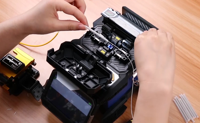
Fabrication fiber:
1. Clean optical fiber coating. Clean the fiber coating with a gauze dipped in alcohol.
2. Fibre optic heat shrink tube. The optical fiber is fully penetrated from the hot melt tube of the heat shrink tube.
3. Stripping and cleaning Peel off optical fiber with skinning forceps, 30-40 mm in length. Cleaning bare fiber with high concentration alcohol .
4. Cutting the end face of optical fiber. Open the plate and place the stripped fiber in the v-groove. Determine the cutting length according to the length required by the operator. Press the press plate to hold the optical fiber lid closed to ensure that the end face of the fiber is in a straight line. Push the tool holder to the back and press the button to open the cutting cover. Take out the cut optical fiber carefully to prevent damage to the fiber end face and clean up the cut fiber. Do not damage the blade for future use.
Placement of optical fibers:
1. Open the windshield.
2. Open the left and right fiber optic plates
3. Placing optical fibers in v-shaped grooves
* ensure that the fiber is not bent when it is put into the welding machine
* if the fiber is curled or bent as a result of the memory effect, the rotation of the fiber causes the uplift to be partially downward
* be careful not to prevent damage and contamination of the end face of the steel wire. Fiber-optic contact with any object, including the bottom of the v-type groove, can result in lower quality.
4. Gently close the optical fiber press to hold it down.
* observation placed in v-type slot Ned optical fiber. The light must be placed at the bottom of the v-type slot. If not, take it out and reposition it.
* the fiber end surface must be placed between the front end of the v-type groove and the center line of the electrode. The end face of the fiber does not have to be placed precisely at the midpoint.
5. Also install second fiber, repeat steps 3 and 4
6. Gently close the left and right fiber press foot
7. Close the windshield
Welding operation:
The button starts the automatic welding procedure, the procedure moves forward the left and right optical fiber automatically. After the arc clean discharge is completed, the fiber will stop at the preset position. When the fiber moves forward and bounces up and down, the v-groove or the surface of the fiber may be contaminated. Clean the v-type groove and remake the fiber. Cutting angle measurement and line alignment operation, when the welding machine in operation or pause, through the naked eye to observe the optical fiber face. (even if there is no error in cutting angle, defects, burrs, sloping should be remade.) When the cutting angle is exceeded, the error message is displayed: "bad fiber end face" or "bad fiber end face", which is also to be recut. After aligning the optical fiber, the welding machine will produce a high-voltage discharge arc to weld the fiber together. During arc discharge, optical fiber images can be observed on the display screen. If some parts of the image show very bright spots, it is caused by the burning of stains attached to the end surface of the optical fiber or the end face, and the core may deform again. Although deformation can be detected by the loss estimation function, rejoining is not recommended. When the welding status is abnormal, the welding machine will display the error message "weld failure". Then refuse. The optical fiber should be tested before welding to select the appropriate state to avoid this phenomenon. If this phenomenon occurs, a new optical fiber test is required. It is normal to have a slightly thicker weld point, and there is no problem with weld loss and reliability. Open the windshield, the welding machine will automatically test the tension and record the results. The connection results will be stored with the welding machine memory chip.
Take out the fiber:
1. Open windshield (heater fixture must be opened, ready to place optical fiber and fiber optic heat shrink tube)
2. Open the left and right fiber press.
3. To remove the optical fiber from the welding machine
Reinforcement of fused joints:
1. Slide the fiber-optic heat shrink tube to the center of the weld and place it in the heater slot. (ensure that fused joints and fiber optic heat shrink tubes are placed in the center of the heater, that the metal body is placed downward and that the fiber is not twisted)
2. While tightening the fiber, lower the fiber and put it into the heater. The left and right heater fixture will automatically close.
3. Cover the heater with the glass cover. (check again to see if the fuse and fiber optic heat shrink tube is in the center of the heater)
4. Keystroke heating. After heating, the heating lamp goes out.
5. Open the left and right heater fixture. Tighten the fiber and gently remove the reinforced fuse.(Sometimes the heat shrink tube may stick to the bottom of the heater. With just one cotton swab or an equally soft pointed object, you can gently roll out the cover.)
6. Observe the bubbles and impurities in the heat shrink tube. (failure to do so again)